On demand. On time.
There is a difference between steel tubes, stainless steel tubes and aluminium tubes.
Steel and Stainless Steel
For steel and stainless steel ducts (square and rectangular), the angles should be drawn as follows:
- outside radius = 2x wall thickness (The value '2' is an average value of the size of the radii mentioned in the standards).
- inner radius = 1x wall thickness.
Aluminium
For aluminium tubes (square and rectangular), the angles should be drawn as follows:
- outside radius = 0 > 0.6 mm radius (acute angle).
- Inner radius = 0 mm radius (acute angle).
247TailorSteel cuts 2.5D. This means that the cutting edge of the ducts is perpendicular to the material (centre-orientation). In case of tubes, it is directed towards the centreline. Some examples are discussed later in this manual. The software of the 247TailorSteel converts the 3D-cutting edges into 2.5D-cutting edges.
Wall thickness options:
Dimension options:
Maximum weight of the product per metre: 32 kg.
Maximum length to be laser cut from one piece: 5,800 mm.
In the case of machining or holes, a minimum size of 0.7 x material thickness is required. This is to ensure the cutting quality.
Refer to NEN-EN-ISO 9013 standard for tolerances for the cutting contour, the centring of the cutting contour and the overall length. . The tolerance is strongly influenced by a number of factors, such as:
When loading the machine, the ducts are loaded randomly (sometimes a complete bundle). This makes it possible that the welding seam can be on different sides of the same product. This means that the welding seam can be on different sides of the same product.
With rectangular ducts, there are 2 possibilities of where the sealing joint can be, either on the short or long sides. We do not know where the joint is beforehand, so it is important to indicate the position of the sealing joint on both sides of rectangular ducts.
Within 12 hours after placing the order, we would like to receive a PDF drawing on which the position of the weld seam and the corresponding position no. of the article are clearly stated. You can send this PDF to service@247tailorsteel.com.
Example - The orange arrow represents the position of the weld seam
The liquid material that forms during laser cutting can attach on the inside of the opposite side; this is also referred to as splash. The dimension of the splash depends on a number of factors:
247TailorSteel only engraves functionally, for positioning or identification. Blind holes are automatically recognized as engraving. If desired, Sophia® can convert a cutting contour into an engraving*.
*Engraving is not possible with aluminum pipes
247TailorSteel cuts 2.5D. This means that the cutting edge is perpendicular to the material (centre-orientation). The software of 247TailorSteel converts 3D-cutting edges into 2.5D cutting edges. This means that a product can be cut different to the drawing. See the examples below for an impression:


Example - drawn image


Example - 2.5D-drawing

Example - drawn image
Holes in round tubes are cut at right angles to the material (centre point). As a result, the holes are cut differently than drawn. Holes that are drawn cylindrically (blue lines in the image) are cut elliptically (orange lines in the image). The diameter of the round hole, measured on the inside diameter of the round tube, corresponds with the diameter of the drawn hole. The diameter of the hole measured on the outside diameter of the tube is bigger and ellipse shaped. These holes are not suitable for, for example, wire tapping.
However, if you require that the hole is cut cylindrically, please inform us within 24 hours of placing the order and provide a clear PDF drawing that explicitly indicates which operations need to be cut cylindrically.
ATTENTION: The diameter of cylindrical holes in round tubes has an upper limit and can not exceed approximately 0.5 x tube diameter.
247TailorSteel cuts 2.5D. This means that the cutting edge is perpendicular to the material (centre-orientation). In case of products that are drawn in mitre, that leads to a groove being created in the outer corner (see images below). These grooves are often filled during welding.


Example - ducts


Example - tubes
U-profiles and segments cannot be cut with 247TailorSteel. In this instance, the system does not recognise a tube or duct. It is important that the full circumference of the tube is present somewhere in the drawing. One of the solutions for this is to draw a “ring” of the starting material alongside and to connect this with a small connection (see images). To this end, please note the available material. To this end, look at the “material summary for tube/duct”. The solutions referred to can also be applied to round tubes. If indicated by the Customer, the additional “ring” and/or the “bridge” can be omitted during laser cutting in many cases.


 In addition, there is the option of choosing to draw an additional “bridge” to get the required full circumference (see image).
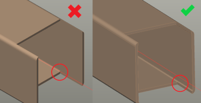
Connections of tubes frequently give problems when drawn in 3D. The online tool, Sophia®, does not always convert the cutting lines correctly, so that the mutual connection of the tubes is not “seamless”. In some cases, this can be solved internally, but new drawings are usually requested. Look at the example below of a 3D-drawing with the products as a result and an example of a tube connection drawn fully in 2.5D.


Example - 3D-drawing and the actual product


Example - 2.5D-drawing and the actual product
PLEASE NOTE!
Every order is unique to us. It is therefore also important that, even in case of recurrent products, the specifications, such as the position of the welding seam or the engraving, are again indicated.
When machining close to the wall thickness, it is important that the machining is at least 0.1 mm from the wall thickness. (see figure)
Example - Minimum distance
The following drawing method requires us to make additional cuts during the process, which may affect the cutting quality. To avoid this, it is recommended to draw the corresponding machining as follows. (see figure)
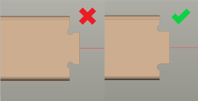
Example - Recommended drawing method
Our new tube laser cutting machines are equipped with a new technology for fitting blind rivet nuts in tubes.

The table below shows at which wall thickness which type of blind rivet nut can be fitted:
| Type | Wall thickness (mm) |
|---|
| 0,5 | 1 | 1,5 | 2 | 2,5 | 3 | 3,5 | 4 | |
|---|---|---|---|---|---|---|---|---|
| M4 | ✔ | ✔ | ✔ | ✔ | - | - | - | - |
| M5 | ✔ | ✔ | ✔ | ✔ | ✔ | ✔ | - | - |
| M6 | ✔ | ✔ | ✔ | ✔ | ✔ | ✔ | - | - |
| M8 | ✔ | ✔ | ✔ | ✔ | ✔ | ✔ | - | - |
✔= blind rivet nut possible
Type ER:

Only available in galvanised steel.
Type FTTE:

Available in galvanised and stainless steel.
| Type | Size (B) |
|---|---|
| M4 | 6 mm |
| M5 | 7 mm |
| M6 | 9 mm |
| M8 | 11 mm |

| Type | Minimum height (H) |
|---|---|
| M4 | 19 mm |
| M5 | 22 mm |
| M6 | 24 mm |
| M8 | 26 mm |


| Type | Minimum height (H) |
|---|---|
| M4 | 21 mm |
| M5 | 27 mm |
| M6 | 31 mm |
| M8 | 35 mm |
| Type | Minimum height (H) |
|---|---|
| M4 | 28 mm |
| M5 | 35 mm |
| M6 | 41 mm |
| M8 | 47 mm |


| Type | Minimum L (mm) |
|---|---|
| M4 | 2 x wall thickness (S2) |
| M5 | 2 x wall thickness (S2) |
| M6 | 2 x wall thickness (S2) |
| M8 | 2 x wall thickness (S2) |
| Date | Change Type | Description |
|---|---|---|
| 20/09/2017 |
| Page published |
| 04/10/2021 |
| Added drawing information |
| 17/01/2022 |
| Updated margins |
| 14/07/2023 |
| Rivet nuts added |
| 12/12/2023 |
| Adjustment tolerances |
