Bending guidelines
Table of contents
Version 1.3 21/04/2020
On demand. On time.
Version 1.3 21/04/2020
Tolerances are always symmetrical relative to the nominal dimension.
S. | A | B | C | D | E | F |
t/m 3 mm | ± 0,2 mm | ± 0,5 mm | ± 0,8 mm | ± 0,5 mm | ± 0,5° | 15′/100MM |
4 mm | ± 0,3 mm | ± 0,6 mm | ± 1,2 mm | ± 0,6 mm | ± 0,5° | 15′/100MM |
5 t/m 6 mm | ± 0,4 mm | ± 0,8 mm | ± 1,6 mm | ± 0,8 mm | ± 0,5° | 15′/100MM |
8 mm | ± 0,5 mm | ± 1 mm | ± 2 mm | ± 1 mm | ± 0,5° | 15′/100MM |
10 mm | ± 0,8 mm | ± 1,6 mm | ± 3,2 mm | ± 1,6 mm | ± 0,5° | 15′/100MM |
Checker plate | 2 mm | 1,5° | ||||
The internal radius is determined by the tools in conjunction with the material properties.
Sophia® will adjust the radii drawn in order to retain the shape of the final product.
For reference, these internal radii can be used for an angle of 90 degrees.
Material thickness | Steel | Stainless steel | Aluminum |
---|---|---|---|
0,8 mm | 1,39 | 1,56 | - |
1 mm | 1,40 | 1,58 | 1,27 |
1,25 mm | 1,42 | 1,57 | - |
1,5 mm | 1,65 | 1,9 | 1,47 |
2 mm | 1,88 | 2,22 | 1,67 |
2,5 mm | 2,41 | 2,94 | 2,11 |
3 mm | 2,75 | 3,75 | 2,50 |
4 mm | 3,02 | 4,48 | 3,3 |
5 mm | 3,62 | 7,82 | 4,07 |
6 mm | 4,62 | 11,91 | 5,34 |
8 mm | 6,97 | - | 6,33 |
Material thickness | Steel | Stainless steel | Aluminum |
---|---|---|---|
0,8 mm | 1,41 | 1,72 | - |
1 mm | 1,35 | 1,62 | 1,28 |
1,25 mm | 1,27 | 1,52 | - |
1,5 mm | 1,19 | 1,42 | 1,12 |
2 mm | 1,3 | 1,59 | 1,22 |
2,5 mm | 1,73 | 2,17 | 1,61 |
3 mm | 2,51 | 3,73 | 2,86 |
4 mm | 2,24 | 3,28 | 2,48 |
5 mm | 2,45 | 5,44 | 2,7 |
6 mm | 3,08 | 8,78 | 3,53 |
8 mm | 4,74 | - | 4,33 |
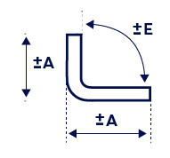
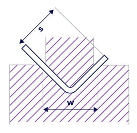
This is the minimum overlay of the sheet on the mold that is necessary to perform the bending. The minimum leg length (b) is determined by the sheet thickness.
All types
Thickness | Groove width (w) | Leg length (b) |
---|---|---|
0,63 mm | 8 mm | 5,60 mm |
0,8 mm | 8 mm | 5,70 mm |
0,88 mm | 8 mm | 5,80 mm |
0,9 mm | 8 mm | 5,80 mm |
1 mm | 8 mm | 5,90 mm |
1,25 mm | 8 mm | 6,10 mm |
1,5 mm | 10 mm | 7,50 mm |
2 mm | 12 mm | 9,10 mm |
2,5 mm | 16 mm | 12,00 mm |
3 mm | 16 mm | 12,40 mm |
4 mm | 24 mm | 17,70 mm |
5 mm | 30 mm | 22,60 mm |
6 mm | 40 mm | 29,60 mm |
8 mm | 60 mm | 42,60 mm |
All types
Thickness | Groove width (w) | Leg length (b) |
---|---|---|
0,63 mm | - | - |
0,8 mm | 8 mm | 5,7 mm |
0,88 mm | - | - |
0,9 mm | - | - |
1 mm | 8 mm | 5,9 mm |
1,25 mm | 8 mm | 6,10 mm |
1,5 mm | 10 mm | 7,60 mm |
2 mm | 12 mm | 9,20 mm |
2,5 mm | 16 mm | 12,10 mm |
3 mm | 20 mm | 15,00 mm |
4 mm | 24 mm | 17,90 mm |
5 mm | 40 mm | 29,20 mm |
6 mm | 60 mm | 41,80 mm |
8 mm | - | - |
S355 rolled blue and CorTen A
Thickness | Groove width (w) | Leg length (b) |
---|---|---|
0,63 mm | - | - |
0,8 mm | - | - |
0,88 mm | - | - |
0,9 mm | - | - |
1 mm | - | - |
1,25 mm | - | - |
1,5 mm | 12 mm | 8,70 mm |
2 mm | 16 mm | 9.20 mm |
2,5 mm | - | - |
3 mm | 24 mm | 16.80 mm |
4 mm | 30 mm | 21,70 mm |
5 mm | 40 mm | 28,70 mm |
6 mm | 40 mm | 29,35 mm |
8 mm | 60 mm | 42,40 mm |
All types
Thickness | Groove width (w) | Leg length (b) |
---|---|---|
0,63 mm | 10 mm | 9,70 mm |
0,8 mm | 10 mm | 9,80 mm |
0,88 mm | 10 mm | 9,90 mm |
0,9 mm | 10 mm | 9,90 mm |
1 mm | 10 mm | 10,00 mm |
1,25 mm | 10 mm | 10,15 mm |
1,5 mm | 10 mm | 10,30 mm |
2 mm | 12 mm | 12,40 mm |
2,5 mm | 16 mm | 15,25 mm |
3 mm | 24 mm | 21,30 mm |
4 mm | 24 mm | 22,00 mm |
5 mm | 30 mm | 22,60 mm |
6 mm | 40 mm | 29,55 mm |
8 mm | 60 mm | 42,35 mm |
All types
Thickness | Groove width (w) | Leg length (b) |
---|---|---|
0,63 mm | - | - |
0,8 mm | 8 mm | 9,90 mm |
0,88 mm | - | - |
0,9 mm | - | - |
1 mm | 10 mm | 10,10 mm |
1,25 mm | 10 mm | 10,20 mm |
1,5 mm | 10 mm | 10,40 mm |
2 mm | 12 mm | 12,45 mm |
2,5 mm | 16 mm | 15,35 mm |
3 mm | 24 mm | 21,50 mm |
4 mm | 24 mm | 22,20 mm |
5 mm | 40 mm | 29,20 mm |
6 mm | 60 mm | 41,80 mm |
8 mm | - | - |
S355 rolled blue and CorTen A
Thickness | Groove width (w) | Leg length (b) |
---|---|---|
0,63 mm | - | - |
0,8 mm | - | - |
0,88 mm | - | - |
0,9 mm | - | - |
1 mm | - | - |
1,25 mm | - | - |
1,5 mm | 12 mm | 11,90 mm |
2 mm | 12 mm | 12,30 mm |
2,5 mm | - | - |
3 mm | 24 mm | 21,15 mm |
4 mm | 30 mm | 21,90 mm |
5 mm | 40 mm | 28,70 mm |
6 mm | 40 mm | 29,35 mm |
8 mm | 60 mm | 42,40 mm |
In order to prevent collision with the tools during a “Z-bend”, it is necessary to take into account the minimum X-measurement shown in the table.
Please note: If the setting is sharper than 90 degrees, then the minimum leg length of a V-groove must be kept wider.
All types
Sheet thickness | Groove width (w) | Leg length (x) |
---|---|---|
0,63 mm | 8 mm | 7,80 mm |
0,8 mm | 8,15 mm | |
0,88 mm | 8 mm | 8,30 mm |
0,9 mm | 8 mm | 8,30 mm |
1 mm | 8 mm | 8,50 mm |
1,25 mm | 8 mm | 8,95 mm |
1,5 mm | 8 mm | 10,65 mm |
2 mm | 12 mm | 13,80 mm |
2,5 mm | 16 mm | 18,80 mm |
3 mm | 16 mm | 20,10 mm |
4 mm | 24 mm | 26,15 mm |
5 mm | 30 mm | 34,65 mm |
6 mm | 40 mm | 42,90 mm |
8 mm | 60 mm | 62,15 mm |
All types
Sheet thickness | Groove width (w) | Leg length (x) |
---|---|---|
0,63 mm | 10 mm | 18,00 mm |
0,8 mm | 10 mm | 18,25 mm |
0,88 mm | 10 mm | 18,40 mm |
0,9 mm | 10 mm | 18,40 mm |
1 mm | 10 mm | 18,60 mm |
1,25 mm | 10 mm | 19,00 mm |
1,5 mm | 10 mm | 19,40 mm |
2 mm | 12 mm | 20,65 mm |
2,5 mm | 16 mm | 25,80 mm |
3 mm | 16 mm | 34,95 mm |
4 mm | 24 mm | 36,50 mm |
5 mm | 30 mm | 40,40 mm |
6 mm | 40 mm | 42,90 mm |
8 mm | 60 mm | 62,20 mm |
All types
Sheet thickness | Groove width (w) | Leg length (x) |
---|---|---|
0,63 mm | - | - |
0,8 mm | 8 mm | 8,35 mm |
0,88 mm | - | - |
0,9 mm | - | - |
1 mm | 8 mm | 8,70 mm |
1,25 mm | 8 mm | 9,15 mm |
1,5 mm | 10 mm | 10,95 mm |
2 mm | 12 mm | 14,20 mm |
2,5 mm | 16 mm | 19,45 mm |
3 mm | 20 mm | 24,75 mm |
4 mm | 24 mm | 27,40 mm |
5 mm | 40 mm | 44,10 mm |
6 mm | 60 mm | 63,20 mm |
8 mm | - | - |
All types
Sheet thickness | Groove width (w) | Leg length (x) |
---|---|---|
0,63 mm | - | - |
0,8 mm | 10 mm | 18,60 mm |
0,88 mm | - | - |
0,9 mm | - | - |
1 mm | 10 mm | 19,00 mm |
1,25 mm | 10 mm | 19,40 mm |
1,5 mm | 10 mm | 19,80 mm |
2 mm | 12 mm | 21,15 mm |
2,5 mm | 16 mm | 26,55 mm |
3 mm | 20 mm | 36,05 mm |
4 mm | 24 mm | 37,60 mm |
5 mm | 40 mm | 44,10 mm |
6 mm | 60 mm | 63,20 mm |
8 mm | - | - |
S355 rolled blue and CorTen A, Z-bend
Sheet thickness | Groove width (w) | Leg length (x) |
---|---|---|
0,63 mm | - | |
0,8 mm | - | - |
0,88 mm | - | - |
0,9 mm | - | - |
1 mm | - | - |
1,25 mm | - | - |
1,5 mm | 12 mm | 12,30 mm |
2 mm | 12 mm | 13,40 mm |
2,5 mm | - | - |
3 mm | 24 mm | 23,45 mm |
4 mm | 30 mm | 31,80 mm |
5 mm | 40 mm | 40,40 mm |
6 mm | 40 mm | 41,15 mm |
8 mm | 60 mm | 60 mm |
S355 rolled blue and CorTen A, Z-bend
Sheet thickness | Groove width (w) | Leg length (x) |
---|---|---|
0,63 mm | - | - |
0,8 mm | - | - |
0,88 mm | - | - |
0,9 mm | - | - |
1 mm | - | - |
1,25 mm | - | - |
1,5 mm | 12 mm | 18,95 mm |
2 mm | 12 mm | 20,15 mm |
2,5 mm | - | - |
3 mm | 24 mm | 33,75 mm |
4 mm | 30 mm | 35,45 mm |
5 mm | 40 mm | 40,35 mm |
6 mm | 40 mm | 41,15 mm |
8 mm | 60 mm | 60 mm |
Due to the rebound of the material, the sheet must always be bent a bit farther than the angle indicated. The tools have a maximum angle of 30˚, which allows for bends of up to 37˚ when you take the rebound into account. The minimum angle to be bent is 175˚.
All types
Thickness | Bend angle |
---|---|
to 4 mm | 37° up to 175° |
5 to 8 mm | 67° up to 175° |
All types
Thickness | Bend angle |
---|---|
to 4 mm | 37° up to 175° |
5 mm to 6 mm | 67° up to 175° |
S355 rolled blue and CorTen A
Thickness | Bend angle |
---|---|
to 3 mm | 37° up to 175° |
4 mm to 8 mm | 67° up to 175° |
If the protruding section is longer than 58 mm, then the corner to be bent cannot be smaller than 70˚ due to collision on the lower beam of the bending machine. If the protruding section is not longer than 58 mm, then the maximum angle is 37˚.
Due to curving and deviations, holes larger than 5 mm may not fall within the leg length of the concerning material type and thickness.
For holes within the minimum leg length, make sure that the sum of the diameters of the holes and/or length of the slots never exceeds 10% of the length of the relevant setting.
Click here for an overview of the minimum leg lengths
If the hole still has to be closer to the bend line, a cut can be made to the bend line.
Do not use a radius greater than 1 mm in the corners of the cut.
Conditions for the cutting line:
Material | Thickness |
---|---|
CRS CR4 | 0,8 up to 3 mm |
HRS 14 HR pickled & oiled | 3 up to 8 mm |
HRS 50F45 pickled & oiled | 3 up to 6 mm |
HRS 14 HR | 2 mm |
HRS 46F40 | 3 up to 8 mm |
HRS 46F40 pickled & oiled | 3 up to 8 mm |
HRS CorTen A | 3 up to 5 mm |
CRS CorTen A | 1,5 up to 2 mm |
AlMg3 EN AW 5754 H111 | 1 up to 8 mm |
AlMg3 ENAW5754 H111 1sc | 1 up to 3 mm |
Sendzimir DX51+Z275 | 0,75 up to 4 mm |
Zincor St12 ZE25/25-03 | 0,8 up to 3 mm |
Brass CuZn37 HH | 1 up to 3 mm |
Magnelis S250 + ZM310 | 1 up to 4 mm |
Material | Thickness |
---|---|
AISI304L 2B | 0,8 up to 6 mm |
AISI304L 2B 1s coated | 1 up to 3 mm |
AISI304L 240Si grit 1s coated | 2 mm |
AISI304L 320Si grit 1s coated | 1 up to 4 mm |
AISI316L 2B | 1 up to 5 mm |
AISI316L 320Si grit 1s coated | 1 up to 3 mm |
AISI430 240 grit 1s coated | 1 mm |
AISI430 finish 2R | 1 mm |
AISI 1.4003 CR finish 2B | 1,5 up to 2 mm |
AISI 1.4003 HR finish 1D | 3 up to 4 mm |
Material | Thickness |
---|---|
AISI304L 2B | 3 up to 5 mm |
AISI316L 1D | 6 mm |
HRS 14 HR pickled & oiled | 8 mm |
HRS 46F40 | 6 mm |
HRS 46F40 pickled & oiled | 6 mm |
AlMg3 EN AW 5754 H111 | 8 mm |
The ability to manipulate the material is largely dependent on the tools used. In order to create U-shapes, 247TailorSteel uses special D-tools. In order to prevent the tools from being overworked, the D10 tools are used to bend U-shapes of up to 5 mm for steel and up to 4 mm for stainless steel. 8mm Steel, 6mm Stainless Steel and 6-8 mm High Tensile Steel are bent with an R-10 tool. However, there is a limit to the feasible width/height ratio of the U shape. See the figures below to determine what the feasible width/height ratio is.
For products as shown in the image, the flange cannot be longer than 32 mm. This is related to the extension (35 mm) of the “horn stamps” that are used to make these types of products.
In order to prevent collision with the machine, the maximum height for box-shaped products is 230 mm.
With similar plates as shown below, corners can be bent up to a maximum of 122˚.
Large or conical radii must be delivered in segments.
Products with this kind of radius are bent in steps, during which the distance between the bends must satisfy the rules for “minimum leg length”.
If a radius is bent conically using multiple consecutive settings, then the bend lines that meet at a “point” can not be drawn as overlapping.
The figure below shows the minimum sizes of stop lugs for the purpose of large or conical radii.
Our narrowest tools are 20 mm. For bends such as those in the image below, this must be taken into account. This is why there must be enough room present for the mold in order to perform the bend.
From a sheet thickness of 4 mm, the width should be at least 22 mm.
In order to bend settings (into corners) such as those shown below, a cut must be made like the one displayed with the red lines.
This cut must be at least the same width as the side to be set.
The sides to be set (corners) cannot be drawn completely against each other due to our tolerances.
We recommend:Always take into account a minimum of 0.5 mm of space between the side to be set and the side that will remain flat.
At 247TailorSteel it is possible to have hemming set. The delivery specifications are as follows:
Material: aluminum, stainless steel and steel
Plate thickness (T): 1 to 2 mm
Minimum leg length (H): 14 mm
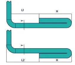
Minimum distance to cant (L1): 6 mm
Minimum distance to cant (L2): 13 mm
Hemming should be requested through your Area Sales Manager.
Date | Change Type | Description |
---|---|---|
13/11/2018 |
| Updated bending information |
26/06/2018 |
| Updated bending information |
20/09/2017 |
| Page published |